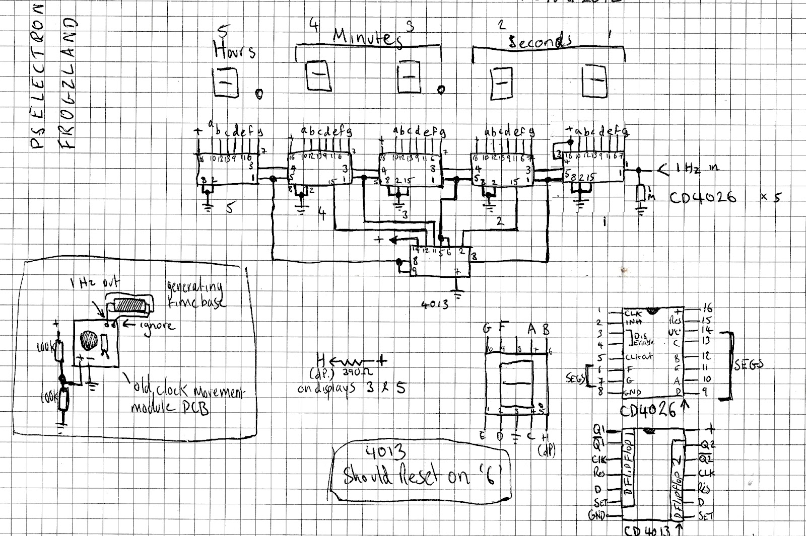
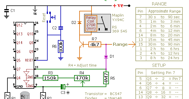
6 Hour Timer Circuit Diagram
1 to 15 minute timer circuit diagram, working and applications Clock circuit digital timer 24 hour diagram microcontroller without projects counter based electronic time simple crystal engineering crcuit electronics Master electronics repair !: 24 hour timer circuit schematic diagram
Master Electronics Repair !: 24 HOUR TIMER CIRCUIT SCHEMATIC DIAGRAM
Timer circuit hour rangkaian 24 circuits cmos diagram off electronic two diagrams control hours elektronika skema jam timers minute schema Timer resistor circuits electricaltechnology pcb 555 cctv clock 24-hour digital clock and timer circuit
Paul in the lab: a word on my schematics and a 10 hour timer
24 hour timer :: circuit diagramsTimer circuit schematics hour lab paul .
.


1 to 15 Minute Timer Circuit Diagram, Working and Applications

Paul In The Lab: A Word On My Schematics and a 10 Hour Timer

Master Electronics Repair !: 24 HOUR TIMER CIRCUIT SCHEMATIC DIAGRAM

24-Hour Digital Clock and Timer Circuit | Best Engineering Projects